Image Banner Source: This picture was courtesy of Chiltern Air Support as cited in [1]
On the 11th of December 2005, a series of explosions and subsequent fire destroyed large parts of the Buncefield oil storage and transfer depot, Hemel Hempstead (UK), and caused widespread damage to neighbouring properties.
The main explosion was of massive proportions, and it was followed by a large fire that engulfed 23 large fuel storage tanks over the Buncefield site. The incident injured 43 people. No one was seriously hurt and fortunately, there were no fatalities. Nevertheless, there was significant damage to both commercial and residential properties near the Buncefield site. About 2000 people had to be evacuated from their homes and sections of the M1 motorway were closed. The fire burned for five days, destroying most of the site and emitting a large smoke plume containing fire combustion products that were released into the atmosphere that dispersed over southern England and beyond.
The Buncefield accident showed us that a tank overfilling scenario cannot be treated as a simple liquid spill. After extensive research conducted by HSE, it was established that liquid cascades tend to fragment into droplets and a proportion of the release forms a vapour cloud that can subsequently disperse. If that cloud encounters a certain level of congestion or confinement, it can potentially explode.
In this blog, I will explain how a tank overfilling phenomenon can lead to the generation of a very flammable vapour cloud, and how this phenomenon can be simulated in Gexcon’s consequence modelling software EFFECTS to ensure that appropriate measures can be taken to avoid this type of catastrophic scenario happening again.
The tank overfilling phenomenon
Following the investigation of the Buncefield incident in 2005, the publication by Atkinson & Coldrick [2] described the mechanism of this tank overfilling phenomenon.
Initial liquid discharge
First, the overfilled liquid overtops the deflection plate and falls as a free cascade (see Figure 1).

Liquid fragmentation
As the liquid stream is accelerated downwards by gravity, it elongates and thins. The surface stress associated with aerodynamic drag increases and the liquid breaks up. The droplets become flattened which increases the drag, and a catastrophic break-up process occurs generating smaller droplets. This flattening and fragmentation of large droplets are so violent that product droplets are flung outwards in all directions. This produces a rapid expansion in the cascade width and is a main driver of the broadening of the cascade throughout its fall.
Developed liquid cascade
The evaporation of the droplets is driven by the concentration gradient between air and the droplets’ surface [4]. At the surface of the droplets, the vapour pressure is at the saturation condition. Once the vapour pressure in the air has reached this level, no further evaporation can take place. As the liquid falls in the cascade, it fragments into spray droplets increasing the surface area of the droplets. Furthermore, vaporization starts to take place in the droplet. The change from the liquid phase to the vapour phase decreases the temperature of the droplet, thus, forming a cold dense cloud of flammable vapour. The water vapour in the air condenses in the cold vapour cloud due to the low temperature of the cloud, producing a visible mist.
Impact zone
Then, at the foot of the tank, the liquid droplets hit the ground forming a splash zone, from which the liquid runs away across the bund floor. The generation of fine splash fragments on impact and the high slip velocities between droplets and vapour lead to greatly enhanced rates of heat and mass transfer in the impact zone. No additional air entrances in this impact zone, but the liquid/vapour system is pushed much closer to equilibrium.
Splash evaporation zone
Finally, since the vapour current is cold and may contain high concentrations of hydrocarbons, the vapour current will be dense and will tend to travel along the ground. If the concentration of the vapour cloud is above its LFL, the cloud may ignite. If the cloud is confined it will also create a vapour cloud explosion (VCE).
Modelling the tank overfilling scenario
Due to the findings from the HSE’s research, it was concluded that a tank overfilling scenario could no longer be treated as a simple liquid spill. That is why, in 2013, HSE published a Technical Note [5] that included a straightforward mathematical approach to simulate the vapour cloud generation due to evaporation from a cascading liquid. Unfortunately, this empirical approach was limited in its application to a few types of fuels, while the associated explosion prediction also restricted its usage to zero wind conditions and specific congestion situations.
The tank overfilling model in EFFECTS
Because the tank-overfilling risks can be relevant to other materials and (weather) conditions as well, Gexcon developed an extended version of this HSE model, which is available in the consequence modelling software EFFECTS.
The extended model incorporates a thermodynamic method to calculate the vapour cloud generation of any overflowing flammable chemical or hydrocarbon mixture. Additionally, the model not only calculates the vaporization rate from the cascade and the slash products generated upon impact against the ground but also includes the evaporation rate from the generated liquid pool at the bottom of the cascade
This EFFECTS tank overfilling model serves as a “source term prediction” method and allows the result to be used as input for a subsequent dense gas dispersion phase, which may be subject to certain wind conditions. Thus, the user can evaluate potential explosion risk in any meteorological and confinement situation. Furthermore, it predicts both cloud and pool contents, providing the possibility to calculate the subsequent pool fire event due to the direct ignition of the remaining liquid spill.
How to simulate the tank overfilling phenomenon in EFFECTS
Would you like to see an example of a simulation of the tank overfilling phenomenon in EFFECTS?
Get started by downloading the project file below, which contains the simulation of a tank overfilling phenomenon, followed by the assessment of the subsequent vapour cloud explosion.
The project file includes the modelling of the tank overfilling phenomenon, which results in a total vaporization rate that can be used for the subsequent dispersion. This total vaporization rate is a combination of the evaporation rate from the falling liquid cascade, from the splash products generated when the cascade impacts against the ground, plus evaporation from the liquid spill generated around the tank.
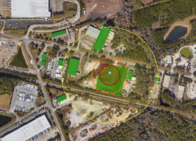
The dispersion phenomenon has been calculated with a dense gas dispersion model, which can be used to assess the potential Vapour Cloud Explosion (VCE), which is highly relevant when the dispersing cloud finds a certain level of congestion.
The VCE has been calculated by means of a user-defined three-dimensional congestion area (i.e., using the GAME overpressure method). The attached EFFECTS file also shows how the tank overfilling model can be connected to a pool fire model, to represent the situation where direct ignition of the remaining liquid spill occurs.

You can open the project file with the EFFECTS’ free viewing demo, available for download via the button below.
[1] The Buncefield Incident. 11 December 2005. The final report of the Major Incident Investigation Board. Volume 1. Buncefield Major Incident Investigation Board. 2005
[2] Atkinson, G. & Gant, S. Buncefield investigation. Liquid flow and vapour production. HSE report RR936. 2012.
[3] Atkinson, G. & Gant, S. Flammable vapour cloud risks from tank overfilling incidents. HSE report RR937. 2012.
[4] Atkinson, G. & Gant, S. Buncefield Investigation. Dispersion of the vapour cloud. HSE report RR1192. 2018.
[5] Technical Note 12. Vapour cloud development in over-filling incidents. FABIG. April 2013.
Do you like what you read?
Get the latest trends in the field of process safety management straight to your inbox, and enhance your skills through knowledge sharing from industry experts.